Casting Terminology

|
| Casting Terminology |
Before studying the sand casting process it becomes important to understand casting terminology.
In the following foundry terminology article, I have discussed casting terms such as flask, parting line, cope, drag, cheek, pattern, bottom board, parting sand, facing sand, moulding sand, system sand and backing sand, pouring basin, sprue, sprue base well, runner, gate, riser, core, chaplets and chills.
Students are advised to read the following casting terminology before studying sand casting.
Flask
|
| (a) Flask |
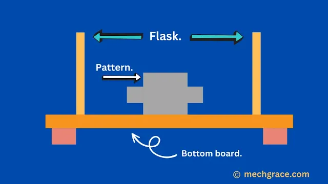
Shown above the flask in diagram (a).
The primary function of a flask is to hold mould intact while making mould and to provide rigidity to the moulding material.
The flask serves as a supporting member to hold mould (cope and drag) during mould mould-making process.
The material used for making flasks is metal or wood depending upon the final application. For large-size casting wooden material is selected as it is more economical than using a metal flask.
A flask is also called a moulding box. Flask used in the foundry are of three types:
- Snap flask.
- Box flask.
- Tapered slip flask.
Parting Line
It is an imaginary line that we assume as shown in diagram (b) above.
The parting line is the imaginary line that divides mould into two parts cope and drag as shown above in diagram (b).
The parting line should be simple and economical running through the centre uniformly and should be straight.
Ideally, the parting line should be at the centre dividing the mould equally but depending on the design of the final casting position of the parting line can change.
When mould is divided into two parts (cope and drag), final casting shares both sides of the mould.
Depending upon the parting line pattern, the gate, runner and risers are accommodated in the mould.
All-time parting lines cannot be straight for casting with complex shapes.
It is not just an imaginary line but serves as a factor that decides the cost of production of casting. Straight line reduces the cost of production of mould as it becomes easy to produce mould and casting as compared to irregular line.
Parting lines also play an important role as a reference point for the placement of gates. For the parting gate, the gate intersects with the parting line in parallel.
Cope

|
| (c) Cope |
The upper part of the parting line is called the cope as shown in the diagram above (c).
If casting is small it can be accommodated in drag only but when casting is large cope is made in the mould for making a bigger casting.
The pouring basin is fully accommodated in the cope section of the mould.
Cope serves an important part of mould while making match plapatternsern, split patterns, multi-ppatternsttern and cope and drag pattern.
Drag
The lower part of the parting line is called the drag as shown above in diagram (d).
During the pit moulding process or making a single piece casting, we can only have drag section in the mould.
In such a casting process (pit moulding) the entire casting is made in drag only.
If only the drag side is utilized for casting components it is observed that the gases from the mould escape better from the mould giving fewer gas defects in the final casting.
Cheek
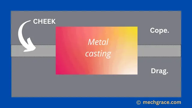
The cheek is part between cope and drag as shown in diagram (e).
Cheek makes mould a three-piece mould.
The cheek is made up of sand and is part of the mould.
Note: Cheek should not be mistaken as a parting line while studying.
Two-piece mould (only cope and drag) is much simpler and more economical than three-piece mould.
Pattern
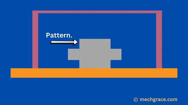
The pattern is a replica of the casting to be manufactured as shown in the diagram above (f).
Molten metal poured into the mould will take the shape of the pattern in the mould cavity.
Patterns can be made up of wood or metal.
A mould cavity is made by placing a pattern on the bottom board, pouring sand over it and then ramming.
I have discussed everything related to patterns in the sand casting process in pattern in casting article.
Bottom Board
The bottom board is used during the sand moulding process and serves as a base for making mould as shown in the diagram above (g).
If the ground or table is uneven bottom board serves as the base while making a sand mould.
The pattern is placed on the board and three types of sand are poured on it. The process is repeated to make drag and cope sections.
The bottom board is made up of wooden material or metal material. This board is a smooth board used as a supporting structure while making a cope and drag section of the mould. The moulding board and bottom board serve the same purpose in making sand-casting mould.
Parting Sand or Parting Compound

|
| (h) Parting Sand |
The parting sand diagram shown above (h) shows sand being used between two halves of the mould.
When mould is prepared it is important that two halves of mould sand (cope sand and drag sand) do not stick together and remain separate.
They are separated by parting sand as shown above in the parting sand diagram (8).
Parting sand can be in two forms: dry and wet.
Examples of dry-parting sand are silicate rock, talc, and charcoal which has a fine structure.
Examples of wet parting sand can be wax-based petroleum jelly and paraffin.
I have written a detailed article on parting sand in sand casting process article.
Facing Sand
|
| (i) Facing Sand |
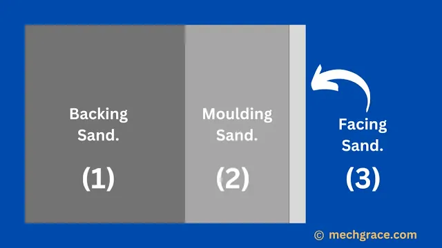
Facing sand is sprinkled on the inner side of the mould cavity.
Diagram (i) shown above is the layer of facing sand marked as notation (3).
This is a skinny layer of carbonaceous material.
This is the sprinkled sand that comes in first contact with the molten metal inside the mould cavity.
Gas is produced when molten metal is in contact with facing sand protecting molten metal from sticking to moulding sand giving a better surface finish.
Quantity and thickness-wise facing sand are lowest if we compare with moulding sand and backing sand.
I have written a detailed article on facing sand in sand casting article discussing facing sand in detail.
Moulding Sand or System Sand

|
| (j) Moulding/System Sand |
Moulding sand is freshly prepared sand and is also called system sand.
The moulding sand layer is shown above in diagram (j) by the notation (2).
Moulding sand is actual sand required to make a mould which covers the casting entirely.
The entire solidification of molten metal happens in close contact with moulding sand.
Moulding sand is higher in quantity and thickness compared to facing sand but lesser when it comes to backing sand.
That is why I have discussed moulding sand in types of sand in the casting process article.
Backing Sand

|
| (k) Backing Sand |
As the name describes, backing sand "backs" both moulding sand and facing sand to create strong support for the mould.
This sand is a supporting layer for moulding sand and the entire mould as shown in the diagram above (k) with notation (1).
This backing sand does not directly come in contact with solidified casting but serves as an important layer for supporting mould and for escaping gasses.
Backing sand not necessarily always has to be fresh sand. This sand can be made from reused and burned sand.
Pouring Basin
The pouring basin is shown above in diagram (l).
The pouring basin looks like a funnel-shaped cavity in the cope and this is where molten metal is poured.
The objective of the pouring basin is to avoid turbulence in molten metal and erosion of the mould.
The pouring basin is located at the core section of the mould and allows the flow of molten metal to the sprue.
I have written a detailed article on pouring basin in casting discussing the design, working and function of pouring basins in the sand casting process.
Sprue
Once the molten metal gets in contact with the pouring basin it travels from the pouring basin to sprue.
Sprue is an important element of mould that controls the flow of molten metal shown above in diagram (m).
Molten metal flowing from the sprue travels to the sprue base well.
I have discussed sprue, types of sprue, design and working in sprue in casting process article.
Sprue Base or Base Well

|
| (n) Sprue Base or Sprue Well |
The base well is designed to reduce sand erosion when molten metal strikes the mould at a higher velocity as shown in diagram (n) above.
Sprue well or sprue base takes all the impact and lets molten metal flow smoothly.
At times splash core is made of ceramic to prevent the erosion of sand.
It serves as a reservoir at the bottom of the sprue as shown in the diagram above.
I have covered sprue base well concept in the sprue in casting article.
Runner

|
| (o) Runner |
The runner is a horizontal passageway/channel that connects the sprue and the gate as shown above in the diagram above (o).
It plays an important role in regulating the flow of liquid metal towards the gate and trap slag.
The outlet of the runner is further connected to the gate where the entry of molten metal takes place in the mould cavity.
Runner, cross sections of runner, design and working are already covered in detail in runner in casting article.
Gate
|
| (p) Gate |
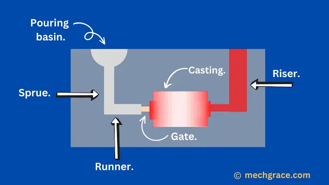
A gate is an entryway by which molten metal enters the mould cavity.
As the name says it is a gate (entry) for the mould cavity shown above in diagram (p).
The location of the gate depends upon the size, shape and complexity of the final casting in the foundry.
I have discussed gate working, gate types, design and diagrams in gate in gating system article.
Cores

|
| (q) Core |
Cores are used to manufacture casting with hollow cavities. Core has the ability to produce holes, passages, hollow sections and counters in sand casting.
As shown above, in diagram (q) cylindrical core in a mould cavity is used to manufacture hollow objects.
In sand-casting cores are made out of sand. Depending upon the application, accuracy and surface finish green sand cores and dry sand cores are selected.
Cores are supported by chaplets which hold the cores during solidification and when metal flows in the mould. Core print is an extension of the core that helps support the core in the mould without the use of chaplets.
Core material, types and working are discussed in core in sand casting article.
Chaplets
Cores cannot be just kept hanging they need to be supported so they do not move when the molten metal comes in contact with them.
The above diagram (r) shows chaplets supporting the core intact.
Chaplets support the core so they do not move, should not buckle, and should overcome the metallostatic force and the core's own weight.
Chaplet in casting is been covered under chaplet in sand casting article with working, diagram and types
I have discussed chaplet used to support core in detail in chaplet in sand casting article with diagrams.
Chills

|
| (s) Chill |
Metal objects are kept in mould cavities so that there is uniform solidification and an increase in the cooling rate for casting as shown above in diagram (s).
As the thickness of the casting is never the same it is essential that both sections cool at the same time to avoid distortion.
This is why chills (metal strips/bars) are placed at the thinner section to achieve uniform solidification.
That is why I have written a complete article on chills in the casting process for a better understanding of the function of chill in casting process.
Riser
A very important element of the casting process is used during liquid solidification when metal is in a solidus state.
The riser is also called the feed head and is considered part of the freezing system and a reservoir.
As shown above, in diagram (t) riser is attached to the mould cavity where molten metal is fed to the casting while liquid solidification takes place.
Depending upon the final casting, the size, shape, and design of final casting the riser are chosen. I have discussed riser in gating system in detail types of risers, and design with diagrams.


